지금 도움이 필요하신가요? 전화주세요!
0573-8553-5198
지금 도움이 필요하신가요? 전화주세요!
0573-8553-5198


Standard pipe flanges — manufactured to ANSI/ASME B16.5, DIN EN 1092-1, JIS B2220, or similar dimensional codes — cover the vast majority of industrial piping applications. For routine connections in conventional pressure classes and nominal pipe sizes, they are the correct choice: readily available, predictable in performance, and straightforward to specify. The problem arises at the edges of those standards.
A pipeline running through a confined offshore platform structure may require a bolt pattern that avoids an existing obstruction. A heat exchanger designed to a legacy specification may use a bore diameter that falls between two standard sizes. A reactor vessel operating at a pressure class and temperature combination that no standard flange covers without over-engineering at significant cost penalty. In each of these situations, forcing a standard component into a non-standard condition introduces either a mechanical compromise or a procurement workaround — neither of which belongs in a critical system.
Custom pipe flanges exist precisely for these gaps. They are manufactured to the exact dimensional, material, and performance requirements of a specific application rather than to a catalog specification. Critically, "custom" does not mean "non-compliant." Standard forged flanges for ANSI and DIN applications follow fixed dimensional tables; custom flanges follow customer drawings — but both are manufactured to the same quality standards, inspection requirements, and pressure integrity expectations.

The scope of customization available in a well-equipped flange manufacturing facility is broader than most buyers initially expect. Almost every dimensional and performance parameter that a standard flange fixes can be modified in a custom program. Understanding the full range helps engineers specify precisely what a project requires rather than compromising to fit available catalog options.
Outer diameter and bore (inner diameter). Standard flanges are tied to nominal pipe sizes. Custom flanges can be produced to any OD and ID combination the pipe system demands, including oversized bores for lined pipe, reduced bores for flow restriction applications, or non-circular bore profiles for specialty connections.
Bolt circle diameter and bolt hole count. The bolt pattern is one of the most common customization triggers. Dual bolt patterns — where a single flange is drilled to mate with two different standard bolt circles — allow connection between mismatched flange standards without adapters. Custom hole counts and diameters address high-load applications where standard bolt spacing is insufficient.
Pressure class and wall thickness. Standard pressure classes (150, 300, 600, 900, 1500, 2500 lb) do not always align with system design pressures, particularly in high-pressure specialty applications. Custom flanges can be designed and tested to any required pressure rating, with wall thickness calculated to the applicable pressure vessel code.
Face type and seating surface. Raised face, flat face, ring-type joint, tongue-and-groove, and male-female face configurations are all achievable. Surface finish (measured in AARH — arithmetic average roughness height) is specified to match the gasket type and sealing requirement of the application.
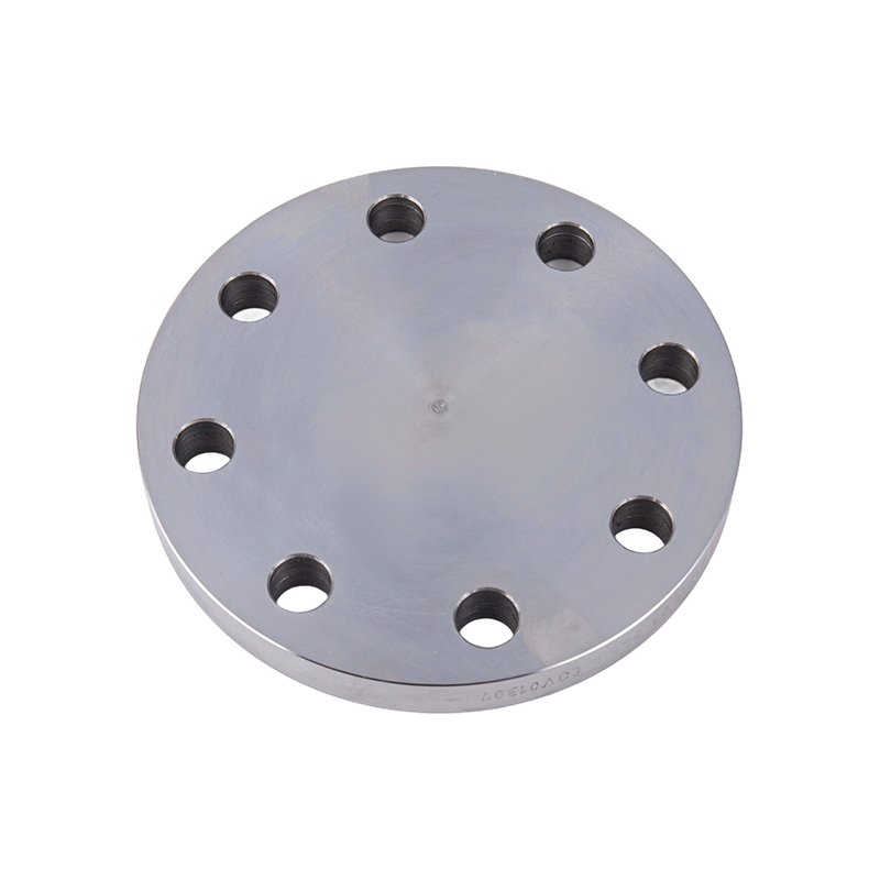
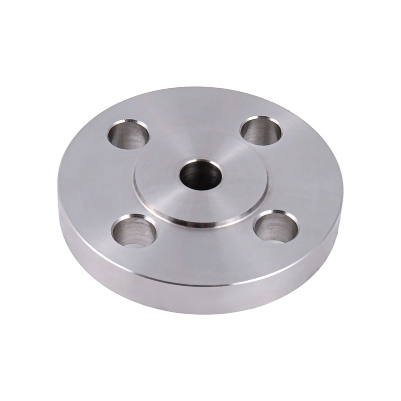
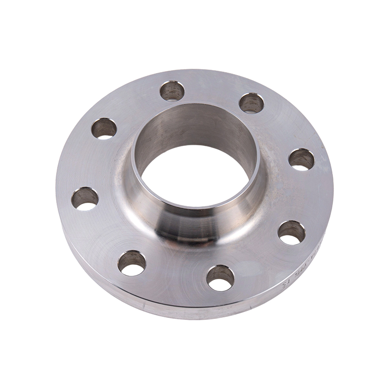
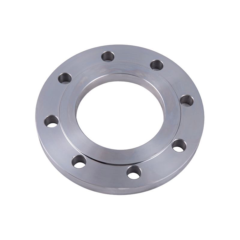
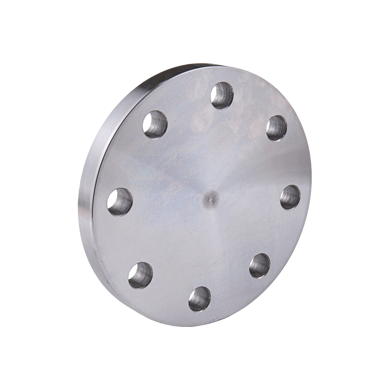
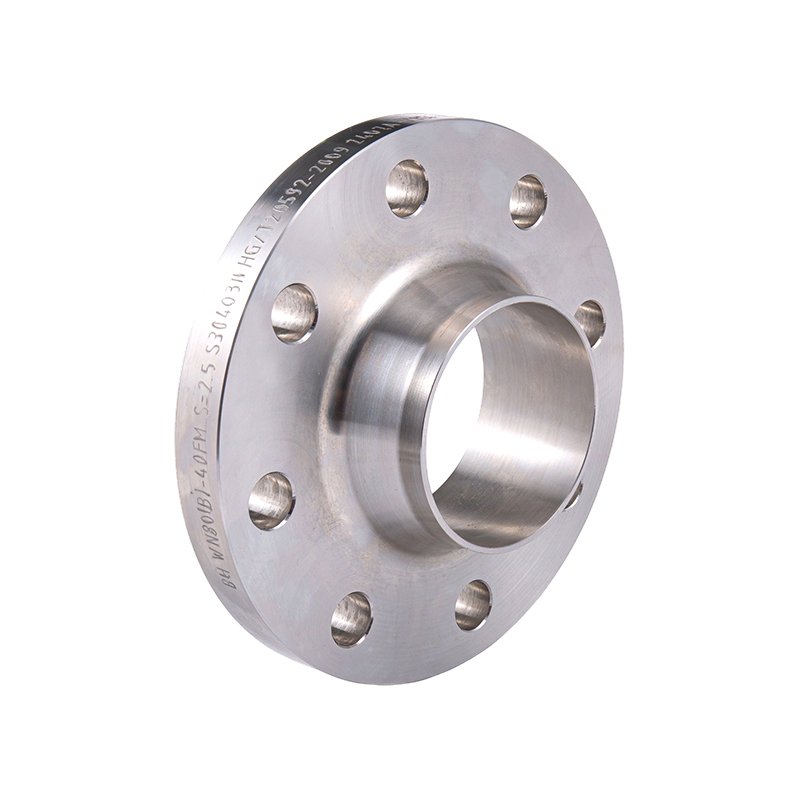
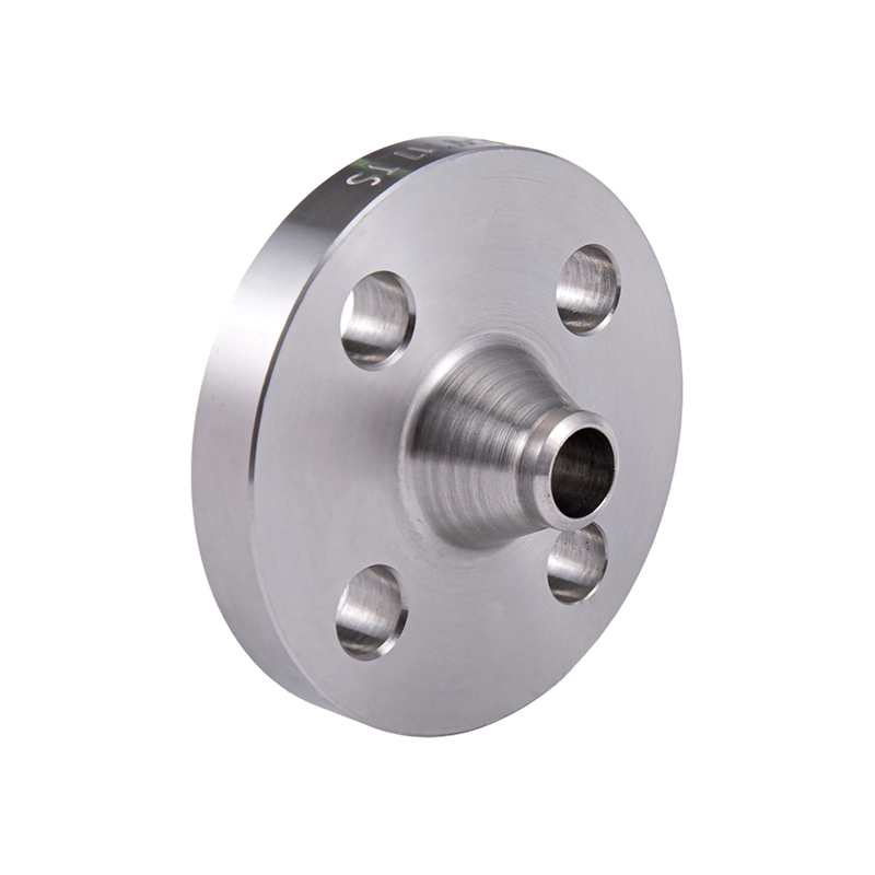
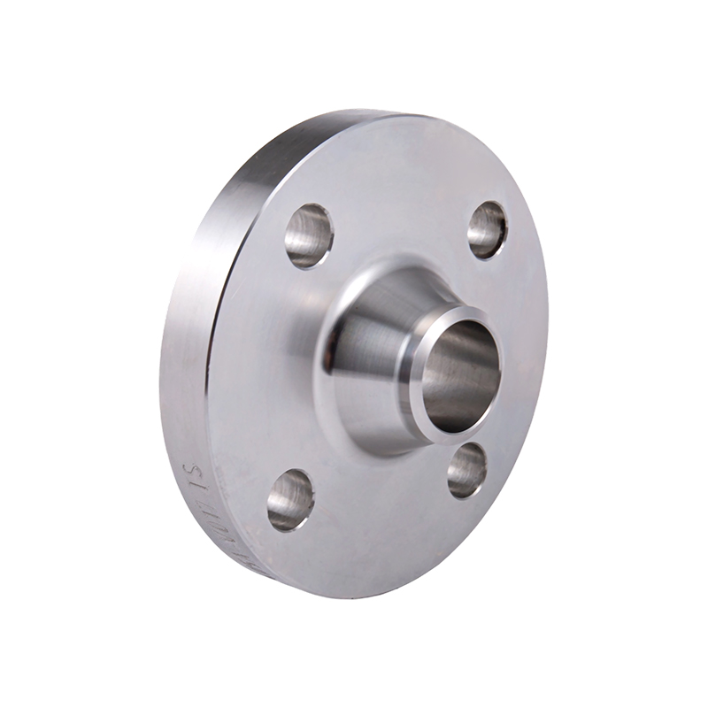
Connection type. Slip-on, weld neck, socket weld, threaded, blind, lap joint, and reducing configurations are all available in custom dimensions. Non-standard variants — such as reducing weld necks, flanges with integral hubs or nozzles, or flanges with internal threading — are produced to customer drawings. These are the applications where non-standard flanges engineered for unique piping configurations deliver value that no catalog product can replicate.
Material choice is frequently the primary driver of a custom flange specification. A non-standard dimension can sometimes be accommodated with a modified standard component, but a non-standard material requirement — driven by temperature, corrosion environment, weight constraints, or regulatory requirements — always leads to custom fabrication. The table below maps common material groups to their application logic:
| Material | Key Properties | Typical Applications | Temperature Range |
|---|---|---|---|
| Carbon Steel (A105, A36) | High strength, low cost, good weldability | Oil & gas pipelines, waterworks, general industrial | -29°C to 425°C |
| Stainless Steel 304/316 | Excellent corrosion resistance, hygienic surface | Chemical processing, food & beverage, pharmaceutical, marine | -196°C to 870°C |
| Stainless Steel 316L | Low carbon, superior weld zone corrosion resistance | Chloride environments, coastal & offshore installations | -196°C to 870°C |
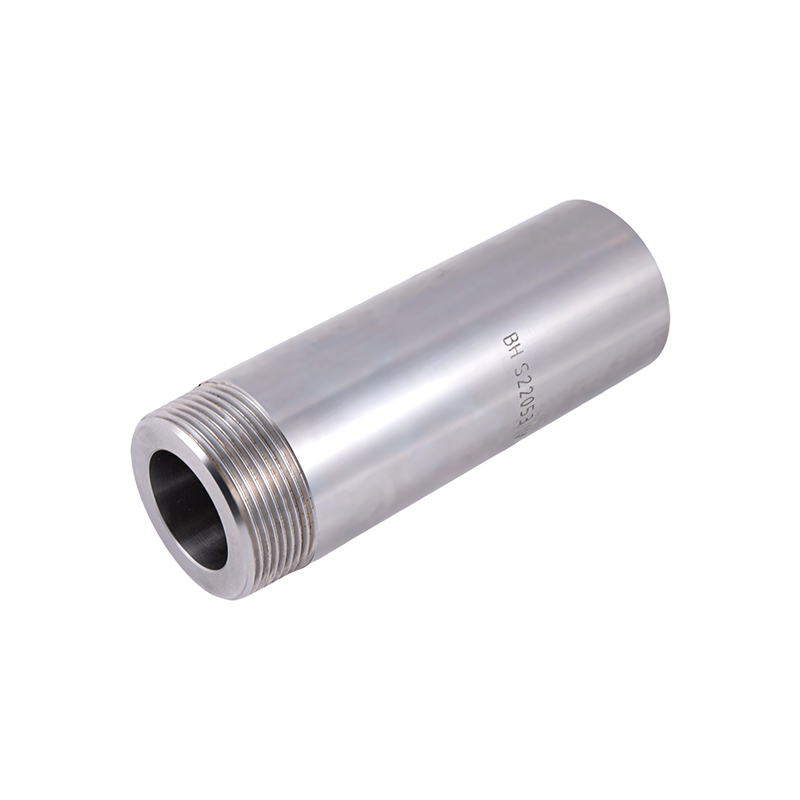
| Duplex Stainless (2205) | High strength + high corrosion resistance, pitting resistant | Offshore platforms, seawater systems, desalination | -50°C to 300°C |
| Alloy Steel (F11, F22, F91) | Elevated temperature strength, creep resistance | Power generation, steam systems, refinery high-temp service | Up to 650°C |
| Nickel Alloys (Inconel, Hastelloy) | Extreme corrosion and heat resistance | Chemical reactors, acid service, cryogenic applications | -253°C to 1000°C+ |
Two considerations beyond base material often shape the final specification. First, heat treatment condition: normalized, quenched-and-tempered, or solution-annealed states affect mechanical properties significantly and must be specified in conjunction with the material grade. Second, supplementary testing requirements: NACE MR0175/ISO 15156 compliance for sour service, PMI (positive material identification) testing for high-alloy grades, and low-temperature impact testing (Charpy) for cryogenic applications are common add-ons that must be confirmed with the manufacturer at the time of inquiry, not after production begins.
Custom pipe flanges appear wherever the combination of operating conditions, regulatory requirements, or system geometry pushes beyond what standard components address. Several industries generate the majority of custom flange demand.
Petrochemical and refining. Refineries and petrochemical plants combine high operating pressures, elevated temperatures, and chemically aggressive process streams — often simultaneously. Standard pressure classes cover many services, but unit-specific designs, legacy equipment interfaces, and site-specific piping standards regularly require custom dimensions. Hydrogen service, in particular, imposes both material and dimensional constraints that standard flanges rarely satisfy without modification.
Power generation. Steam turbine systems, boiler feed lines, and high-pressure extraction piping operate at temperatures and pressures that push against the upper limits of standard flange ratings. Main steam flanges in modern combined-cycle plants commonly require alloy steel grades and custom geometries to mate with turbine nozzles and valve bodies that are themselves custom-engineered components.
Marine and offshore engineering. Salt water corrosion, space constraints in shipboard piping runs, and the weight sensitivity of offshore topsides all create custom flange requirements. Duplex stainless steel flanges with non-standard bolt patterns to suit vessel-specific piping arrangements are a routine output of marine engineering projects. For complete system solutions, flanged pipe fittings for complete piping system solutions are often specified alongside custom flanges to maintain consistency across the entire piping assembly.
Water treatment and waterworks. Large-diameter water transmission pipelines — particularly those transitioning between AWWA-standard pipe and ANSI-standard valves or meters — generate a consistent demand for custom flanges that bridge dimensional standards. Custom reducing flanges and dual-drilled flanges are common in pump station and water treatment plant piping.
Food, beverage, and pharmaceutical. Sanitary piping systems demand flanges with specific surface finishes (typically Ra ≤ 0.8 µm), crevice-free internal geometry, and materials compliant with FDA and EHEDG requirements. Standard flanges rarely meet all three conditions simultaneously, making custom sanitary flanges in 316L stainless steel a standard procurement item in these industries.
Understanding how a custom pipe flange moves from specification to finished component helps buyers set realistic expectations for lead times, minimum order quantities, and quality documentation requirements.
Design review and drawing confirmation. The process begins with the customer's drawing or dimensional specification. A competent manufacturer will review the drawing for manufacturability, flag any dimensional conflicts or standard compliance issues, and confirm the specification before committing to production. For complex geometries or unusual material grades, this stage may involve back-and-forth on tolerances and surface finish requirements — time well spent before raw material is committed.
Forging. For flanges requiring high mechanical integrity — particularly weld neck flanges, high-pressure service components, and any application covered by ASME Section VIII or equivalent pressure vessel codes — forging is the correct manufacturing route. The forging process aligns the grain structure of the metal with the flange geometry, producing superior strength, fatigue resistance, and pressure integrity compared to plate-cut or cast alternatives. Material certifications (mill test reports, heat number traceability) are generated at this stage and follow the component through the entire production chain.
Machining. After forging, the flange blank is machined to final dimensions. CNC turning, milling, boring, drilling, and facing operations produce the bore, bolt holes, face type, and outer profile to the tolerances specified in the customer drawing. Surface finish of the seating face is measured and documented. For flanges requiring tight dimensional tolerances — such as ring-type joint faces or precision bore applications — this stage is where manufacturing quality is ultimately determined.
Inspection and testing. Custom flanges are subject to the same inspection protocols as standard components: dimensional verification, visual inspection, and material verification as a minimum. Depending on the specification, additional testing may include hydrostatic pressure testing, dye penetrant or magnetic particle inspection for surface defects, ultrasonic testing for internal integrity, and hardness testing for heat-treated components. All test results are documented and provided with the shipment.
Surface treatment and delivery. Flanges are typically supplied with a rust-preventive coating for carbon steel grades, or in the as-machined condition for stainless and alloy grades. Special coatings — epoxy, galvanizing, or nickel plating — are applied where the service environment requires additional protection. Flanges are packaged to prevent dimensional damage to seating faces during transit, with flange face protectors standard for all raised-face and RTJ configurations.
The speed and accuracy of a custom flange quotation depends almost entirely on the completeness of the information provided at inquiry. Incomplete specifications generate clarification loops that extend lead times and introduce the risk of production errors. The following checklist covers the parameters a manufacturer needs to quote and produce a custom pipe flange without ambiguity:
| Parameter Category | Specific Information Required | Notes |
|---|---|---|
| Dimensional drawing | OD, ID (bore), thickness, bolt circle diameter, bolt hole count and diameter, face type and finish | DXF, DWG, or PDF format; include tolerances on all critical dimensions |
| Connection type | Slip-on, weld neck, blind, threaded, socket weld, lap joint, or non-standard variant | Specify hub dimensions for weld neck; thread specification for threaded types |
| Material grade | ASTM/EN grade designation and heat treatment condition | e.g., ASTM A105 N, ASTM A182 F316L, EN 1.4462 (duplex) |
| Pressure rating | Design pressure (bar or psi) and design temperature | Or applicable pressure class if referencing a standard |
| Applicable standard | ASME B16.5, B16.47, EN 1092-1, or "to drawing" if fully custom | Determines which dimensional and testing requirements apply |
| Testing requirements | Hydrostatic test, PMI, impact testing, NDE method, NACE compliance | Specify acceptance criteria and required documentation |
| Surface treatment | As-machined, rust preventive, epoxy coated, galvanized, or other | Specify coating thickness if applicable |
| Quantity and delivery | Order quantity and required delivery date | Larger quantities reduce unit cost; confirm minimum order requirements |
A dimensioned drawing, even a hand sketch with all critical dimensions annotated, is worth more than a detailed written description. Manufacturers work from geometry, not prose. For projects involving multiple custom flange types across a single system, submitting a complete bill of materials at the outset — rather than inquiring for each item separately — typically yields faster turnaround on both quotation and production scheduling, and often better pricing on the complete package.
영어
QR코드